|
Why Do I See a Keil License Failure If I Connect the E5 JTAG Cable? The following problem only occurs when using the “dongled” version of the Keil tools, which requires that a “security block” be connected to your computer’s parallel port. If your version of Keil does not require a security block, you may ignore this article. This problem occurs if you connect the E5 JTAG download/debug cable to the Keil dongle. Signals sent to the Keil software to the dongle interfere with the JTAG circuitry on the E5. Typically, the Keil software will launch in evaluation mode because it did not accurately detect the dongle. Here are a few possible solutions. Using a Second Parallel PortIf your computer has two parallel ports, you can place the Keil dongle on one port and the E5 JTAG download/debug cable on the second port. The Keil support web site has detailed instructions on using another port for the Keil dongle. UV2: USING DONGLES WITH LPT2
OR LPT3 Download via Another PC On Your NetworkTriscend FastChip is designed so that your download and debugging tools operate over your internal network. You can develop on one computer and download using the parallel port on another computer attached to your network. See article 22224, “Can I Download and Debug via a Remote PC?” Contact Keil for Possible Other SolutionsYour Keil sales office may be able to provide alternate solutions such as a USB-based key. Under some circumstances, you may be able to obtain a version of Keil that does not require a dongle. This must be arranged through your local Keil sales office. Modifying the Cable Hardware
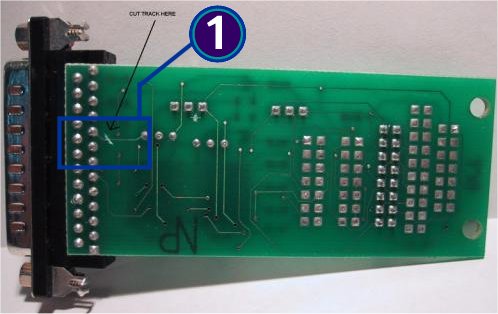
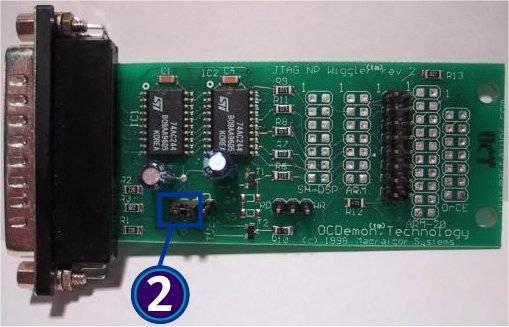
© 2001-2002 by Triscend Corporation. All rights reserved. |